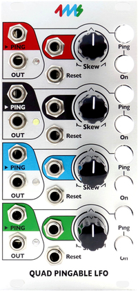
| Quad Pingable LFO [Full Kit] |
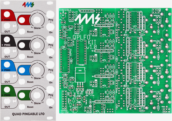
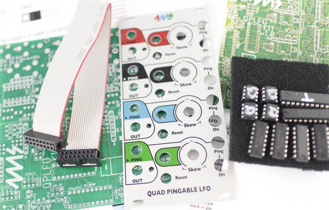


Build your own Quad Pingable LFO, with the QPLFO kit.
The Do-it-yourself kit includes all the parts necessary to build a fully-featured QPLFO. This is an advanced-level kit, so you should be experienced in soldering and have basic hand tools (flush snips, needle-nose pliers, small screw driver).
Basic features
- Quad "pingable" LFO's -- frequency is set by time between pulses ("ping")
- Each of the 4 channels is an independent LFO
- Can produce a variety of waveshapes: "Pluck," to ramp-down, to triangle, to ramp-up, and all shapes in between
- Channels can easily modulate, trigger, and reset each other for complex and slowly morphing outputs
- Slowest period is about 71 minutes (0.0002 Hz), fastest speed is about 500Hz (marginal tracking up to 1kHz)
- Tap tempo button is free-running (LFO runs indefinitely), but external clock/Ping is auto-stopping (LFO stops when external clock stops)
- Tap tempo button ("Ping") for manually setting the tempo
- Ping jack sets tempo with an external clock (any complex signal can be used as a clock)
- On/mute button enables or mutes the output (latching button)
-
Skew knob and CV jack control the waveshape by altering the ratio between rise and fall times
- At 0% Skew (0V of CV), the shape is a "plucky" near-expo curve
- At 1% Skew (just over 0V of CV), the shape is ramp-down
- At 50% Skew (about 5V of CV), the shape is a triangle
- At 100% Skew (about 10V of CV), the shape is ramp-up
- Skew knob provides offset to the incoming CV signal, so any range of CV is acceptable
- Reset jack restarts the LFO without changing the tempo (rising edge triggered)
- OUT jack outputs either a 0 to 10V waveshape, or a -5V to +5V waveshape (jumper selectable)
- LED flashes and dims to the signal on the OUT jack
- Tap tempo button flashes to the internal tap-tempo clock or to incoming pulses on the Ping jack
- On/Mute button lights up when channel is On
-
Ping and Reset inputs use comparators, so any waveshape can be used for triggering (audio waves, complex LFOs, even the QPLFO itself!)
- Trim-pot on PCB allows for adjustment of comparator threshold value
-
"Fire-on-unmute" jumper per channel:
- When this optional jumper is installed, pressing the On button to turn the channel on will reset the LFO.
- If the jumper is not installed (factory default), pressing On will unmute the LFO without resetting (LFO runs in the background when muted)
-
Bipolar/Unipolar jumper:
- Setting jumper to Bipolar makes the outputs -5V to +5V
- Setting jumper to Unipolar makes the outputs 0V to +10V
- One jumper controls all four channels
- One-shot mode: Reset jack can be used to trigger a one-shot envelope if the external ping clock is stopped. See manual for detailed discussion
- Floating Reset mode: Holding a high gate on Reset jack allows the waveshape to run freely without automatically re-syncing to the ping clock. A bare cable plugged into the jack causes a high gate
-
Connects to other modules using ribbon cables:
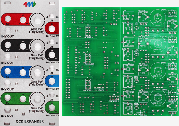
- Outputs can connect to the 4ms VCA Matrix, or the 4ms SISM, the Circuit Abbey Intermix or the Toppobrillo Mixiplexer
- Normalization of ping jacks can connect to the 4ms Quad Clock Distributor
Module size:
The QPLFO is 12HP and 1.57 inches (40mm) deep.
Power consumption:
A jumper selects using +5V from the power supply, or generating +5V on-board from the +12V rail.
- +12V rail:
- 89mA max with jumper selecting external 5V
- 154mA max with jumper selecting internal 5V.
- +5V rail:
- 65mA max with jumper selecting external 5V
- not used (0mA) with jumper selecting internal 5V.
- -12V rail:
- 73mA max